 BACK TO FM TRANSMISSION
 30W to 1200W
 RF Amplifier
 4kW to 80kW
 30W and 50W
 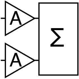 RF Amplifier
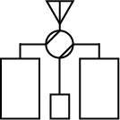 N+1 Controller
 Network
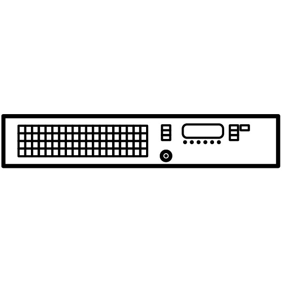 Digital DDS
 Remote Control
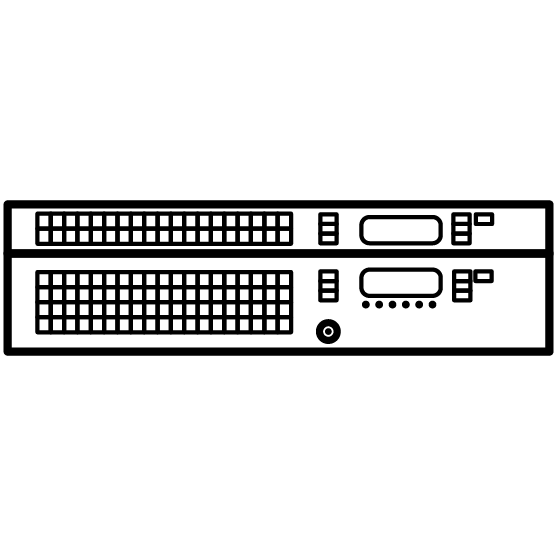 1000W to 5000W
N+1 Automatic Change-Over Controller
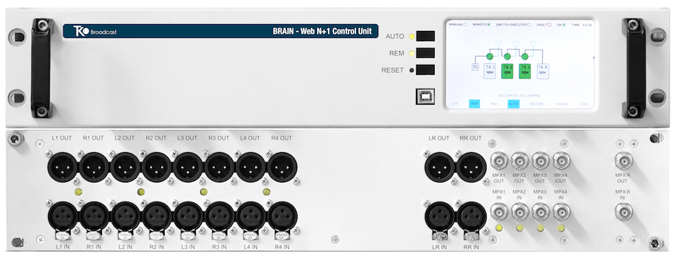
WCU 6+1 and MTX-AUD 6+1 N+1 Fully Web
and SNMP WEB Control Unit
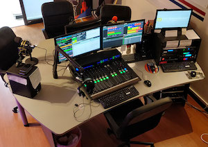
System
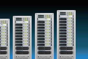
TEKO Broadcast offers extremely reliable N+1 systems in a complete turnkey solution with rack integrations, personalized and compact.
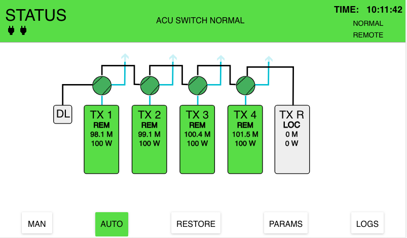
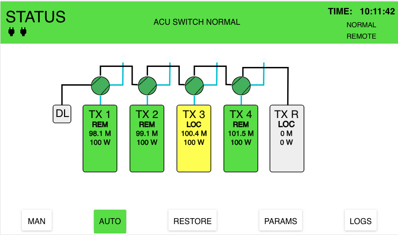
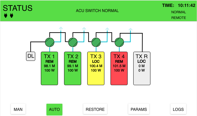
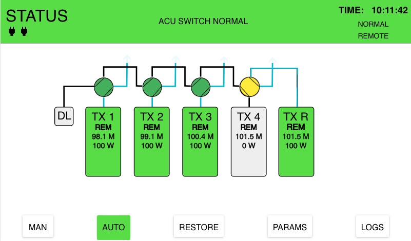
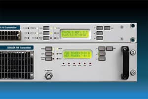
The N+1 Automatic Change-Over Controller can manage up to 8 FM programs
(up to 8+1 systems).
Thanks to the use of the standard SNMP protocol,
any anomaly of the main transmitter is detected
automatically by the switch of the automatic Nf+1 shift controller, that changes to the backup transmitter.
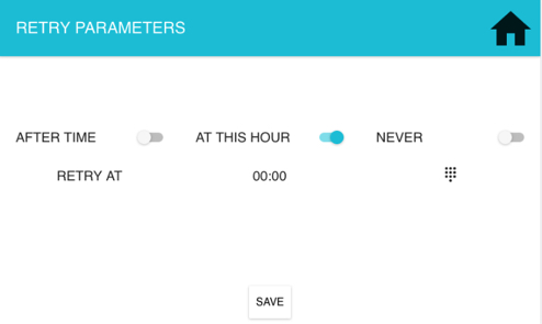
Our system is smart, and all the parameters related to the
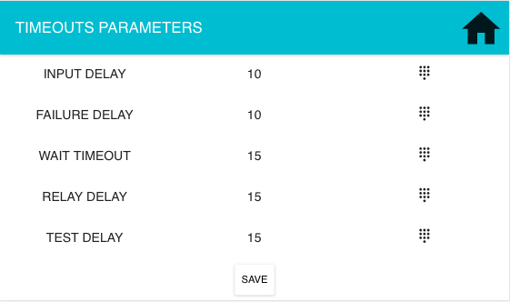
time limitations, program priorities, switching conditions,
etc., are fully configurable.
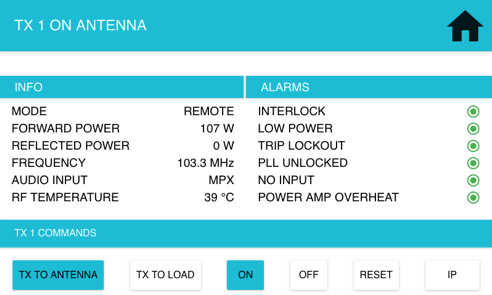
The controller is fully equipped with all interface
security loops, CAN bus and RF switches (from N to 1/5/8).
The N+1 Automatic Change-Over Controller offers a
full control through its intuitive web interface, and for
local and manual operations the front panels offer easy access,
quick and easy via displays, status indicators and buttons
for manual change or other actions.
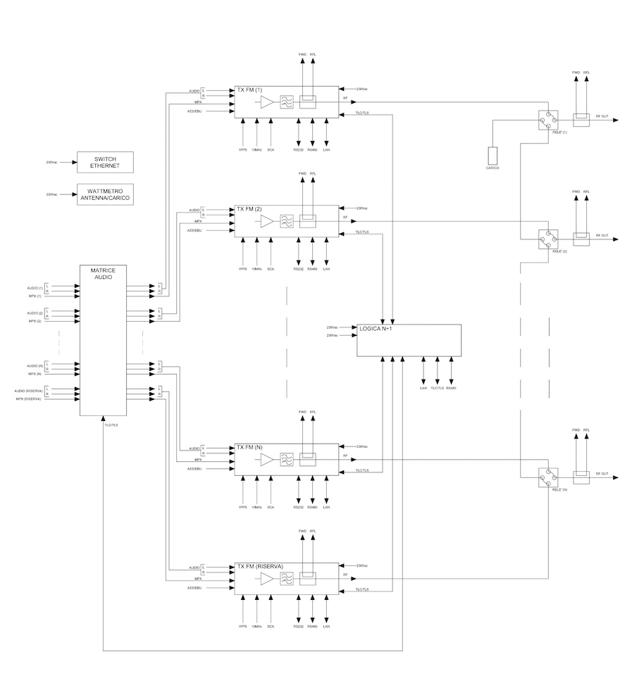
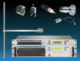
Components of the Automatic N+1 Change-Over Controller
An N+1 system is made up of:
- N main FM transmitters, of any power, in D.E. or 1+0.
- A standby transmitter (or +1) that must be able to operate at the frequencies and configurations of the N main transmitters.
- N Coaxial switches that allow the exchange of RF signals to the antenna, between the main transmitters and reservation.
- An N+1 UCA (Automatic Switching Unit) capable of manually or automatically, locally or remotely manage the N+1 system.
- An input preselector that allows selection and switching of the audio signals of the N transmitters to the backup transmitter.
- An interconnection kit between all the elements that make up the N+1 system. This kit consists of the specific wiring and any additional cards, such as those described in the Minimum specifications section of the interlock circuit of the N+1 system. Auxiliary cards.
- An artificial charge whose power capacity is 25% greater than the greatest power of the N transmitter system.
- OPTIONAL: RF sensors, external and independent of the transmitters, capable of remotely signalling – by contacts free of voltage – both correct and incorrect RF levels (both independently adjustable). Additionally, it would be desirable that these sensors be capable of delivering a direct and reflected power telemetry of the system. An east external element, only considered necessary in case the N main transmitters do not obtain this information through contacts.
Description of the N+1 Automatic Change-Over Controller
The system is governed by an N+1 Automatic Change Over Controller, which supervises the operation of the rest of elements.
In the event of an N transmitter failure, this System must be capable to act on: the main transmitter that has failed, the reserve (+1), the coaxial switches and the audio preselector, to get the reserve transmitter to broadcast on the antenna (or B.E. of the multiplexer), corresponding to the transmitter that has failed, with all parameters of power, frequency, program (audio) and any other transmitter configuration parameters linked to the ones it substitutes.
It must be taken into account that in a chain of N transmitters there can be different powers for different services. The standby transmitter must be capable of operating in each case with all the correct parameters.
Main Features of the N+1 Automatic Change-Over Controller
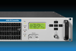
- Touch Screen Control Logic
- Configurable from 2+1 up to 6+1 and 1+1
- 6 different priority levels
- Local or remote operation
- Automatic or manual operation
- All switching parameters and timings are configurable
- It can control Transmitters of any brands and models
- Front panel with high definition Color TouchScreen display, for an immediate and intuitive control of the overall system
- Direct access keys to control the most important parameters
- “RESTORE” button to bring the system to the default configuration
- Configurable in Less than 1 second switching time
- Remote control through standard parallel interface (TLC/TLS), IEE485/RS232, TCP/IP
- Web server and SNMP protocol
- Dry contact relay outputs
- Opto-isolated inputs
- Inputs and outputs powered by separate and electrically isolated power supply
- Dual Redundant power supply
6+1 Block Diagram System