 BACK TO FM TRANSMISSION
 30W to 1200W
 RF Amplifier
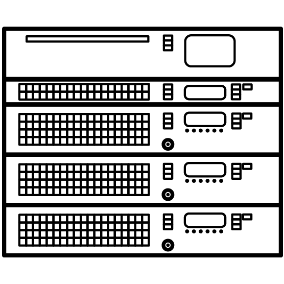 4kW to 80kW
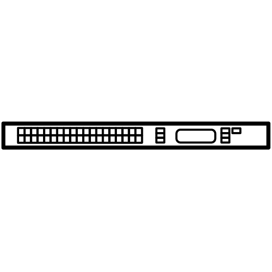 30W and 50W
 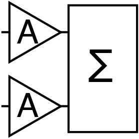 RF Amplifier
 N+1 Controller
 Network
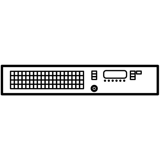 Digital DDS
 Remote Control
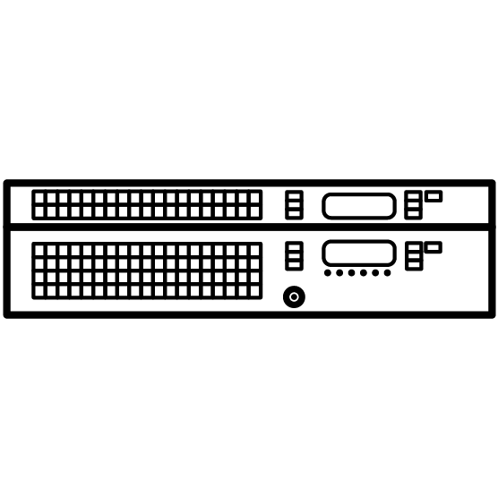 1000W to 5000W
CORTEX FM Transmitters combine low energy consumption, exceptional reliability, and advanced connectivity. Their sound is warm and clear, thanks to a high-fidelity design with very low distortion, excellent stereo separation, and a high signal-to-noise ratio.
Composed of 2 to 40 amplifier modules CORTEX are DRM and IBOC ready.
Main Key Features
- Output Power from 5kW to 80kW
- Modular Architecture
- Double Drive option
- Extreme Robustness and Reliability
- Easy maintenance and low-cost ownership
- Remote Access via HTML5 Web, TCP/IP, SNMP, Email, and Telegram
- Unmatched Audio Fidelity and Versatile Audio Inputs
- Exceptional efficiency and low power consumption
- Minimal Impact on Output Power in Case of RF Amplifier Failure
- Fully redundant RF amplifiers, power supplies and double exciter.
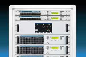
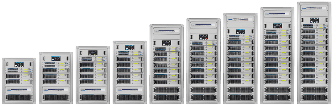
CORTEX FM transmitters range from 5kW to 100kW by combining 2 to 40 RF amplifiers. Its modular design simplifies maintenance by housing each component: Exciter, RF Amplifiers, Splitters, Combiner, Unbalanced Power Load, Control Logic, Rack and Breakers in separate cabinets.
Explore other TEKO FM transmitters
- Back to the homepage to explore our complete line of FM transmitters and equipment for studios and radio station sites.
- All FM Broadcast Transmitters (low, medium, and high power)
- Low Power FM transmitters (30W-5kW) - Compact Architecture.
- Medium Power FM transmitters (2kW-5kW) - Esciter and RF Amplifier Architecture.
- High Power FM transmitters (5kW-100kW) - Modular Architecture.
Highlights
- High SNR (85 dB), stereo separation (65 dB), ultra-low distortion (0.01%)
- Supports MPX, Stereo, AES/EBU, Mono, Dynamic RDS, IP streaming, USB/HD playback
- Intelligent Soft Limiter: 75 kHz deviation without distortion
- Smart Efficiency Algorithm: Dynamic DC voltage and bias control for optimal efficiency across frequencies and power levels
- Weekly Power Derating Scheduler optimizes energy consumption by allowing multiple configurable power settings for each day.
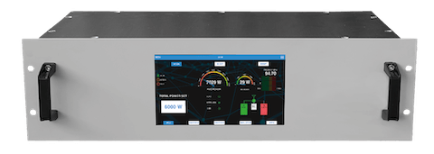
- Touch Screen BRAIN WEB Unit
Plug-In Power Supply
The most reliable Power Supply of the market
WEB Remote Control
- Remote access via TCP/IP through Web interface and SNMP v1/v2 sends real-time status and alarm notifications via email and Telegram.
- Notifications are fully configurable for immediate alerts or periodic updates at defined intervals.
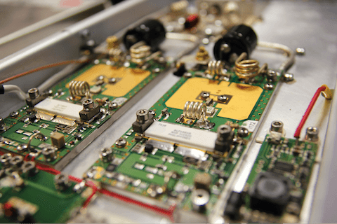
Planar Design
- Planar Design: Improves thermal management and layout compactness
- Up to 88% RF and 79% total efficiency
- Robust 50 V LDMOS, 6th gen planar tech, VSWR tolerance > 65:1
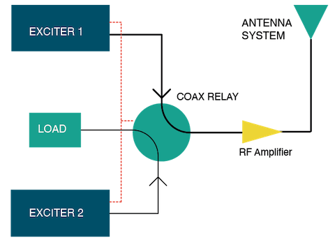
Example of block diagram of CORTEX 10kW FM Transmitter
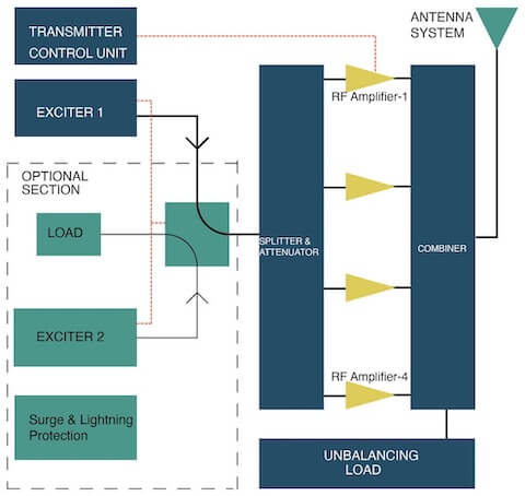
MODULAR ARCHITECTURE
Advantages:
Other manufacturers integrate the combiner, splitter, unbalanced dummy load, and control logic into a single enclosure. This architecture reduces reliability because all transmitter functionality depends on a single device. Moreover, maintenance becomes highly difficult: any fault requires disassembling the entire transmitter and disconnecting it from the antenna, making access to these components complicated.
In the CORTEX modular system, each component has an independent enclosure and is installed in the most convenient position to simplify connection and maintenance, facilitating troubleshooting and fault resolution.
Additionally, its modular architecture allows CORTEX to use the same components across its entire power range, ensuring consistency in spare parts.
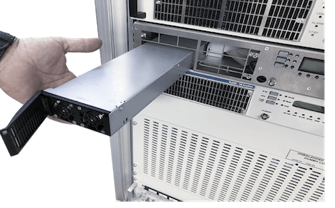
Another key advantage is that the RF amplifier is designed to operate independently and includes all
necessary
elements: power supply, fans, control logic, output filter, and protections.
Testing or repairing it—either on-site or in the lab—requires only an external exciter, dummy load, and a standard power cord, with no special tools needed.
By combining two or more CORTEX 25/10 units, power levels up to 100kW or more can be achieved.>
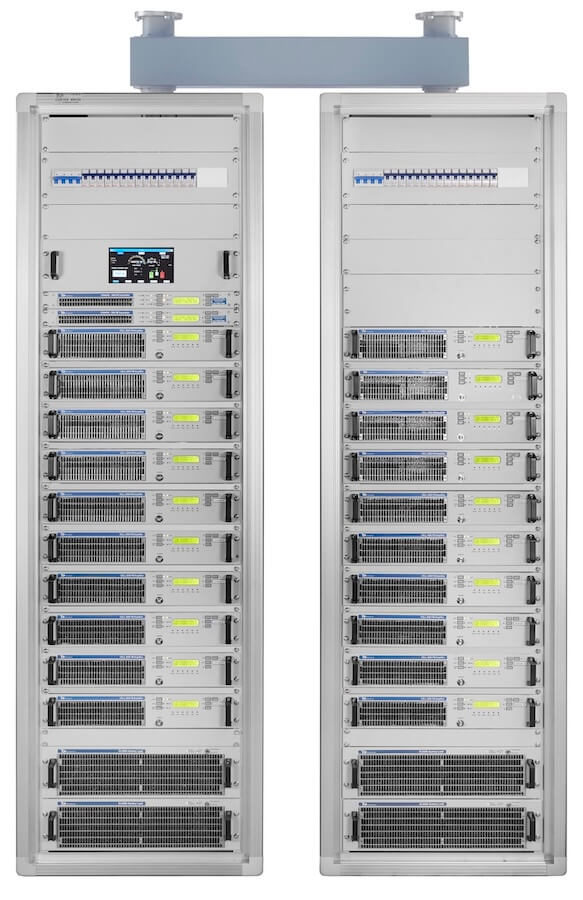
For example, the CORTEX 50kW system is composed of:
Modules of the Modular 50kW Transmitter:
- 2 x 25kW RF amplifiers
- 1 x 3dB hybrid coupler
- 1 x 15kW dummy load
- Double Exciter SYNAPSE 30
- 1 x Touch Screen BRAIN WEB Control Unit
The 50kW FM Transmitter is composed by two 25kW Gyrus FM amplifier’s
Modules of the 25kW RF Amplifier:
- 20 x 2500W CELL RF Amplifiers
- Double Exciter SYNAPSE 30
- 10 output Power Splitter
- 10 input Power Combiner
- 2 x 5 input Unbalanced Power Load with External Power Supply
- 42U Rack
- Main Breakers
- Overvoltage Surge Protection and Delayed Energization (Optional)
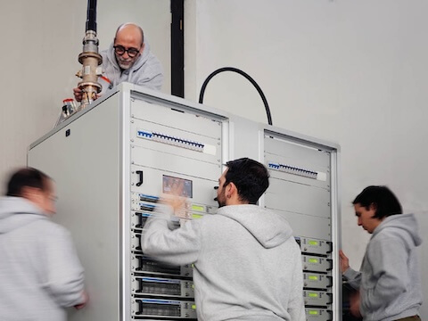
CORTEX 50kW FM Transmitter
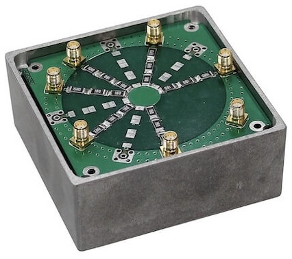
Multiport Power Splitter
Divides input power into multiple outputs, with configurations ranging from 2 to 10 outputs. The input includes a 50Ohm attenuator/isolator, ensuring a constant and matched load to the exciter. This is crucial for maintaining system redundancy. Without it, a fault in the splitter, a cable, or an amplifier’s input could trigger a VSWR alarm on the exciter, potentially shutting down the entire transmitter.
Multiport Combiner
- Revolutionary Modular Design
- Ultra-Compact Design
- Direct Scaling: Stepping from low power to high power.
- Low Loss Performance: Less than 0.1 dB loss.
- Flexible Configurations
- Ground-Referenced Balancing Loads
- High Isolation Value: Over 26 dB.
- Supports Up to 10 Input Ports
- Ultra-Wideband Design
- Phase Stability
- Additive Harmonic Filtering: More than 12 dB.
- Excellent Cost-to-Power Ratio
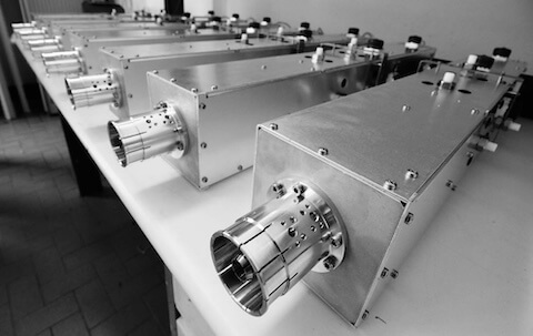
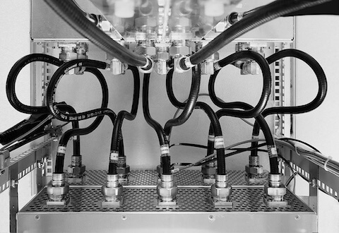
10 inputs to 1 x 3 1/8 inch Multiport Power Combiner
Combines 6 to 10 RF Modules to obtain up to 25kW output power.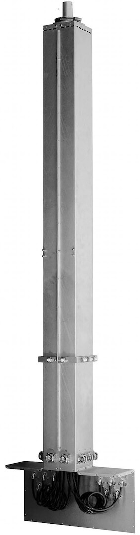
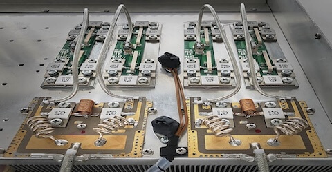
2 x 3 1/8 inputs to 4 1/2 inch Hybrid Power Combiner
Combines 2 RF Amplifier to obtain up to 50kW Output Power.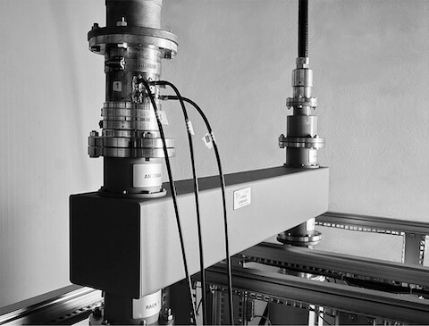
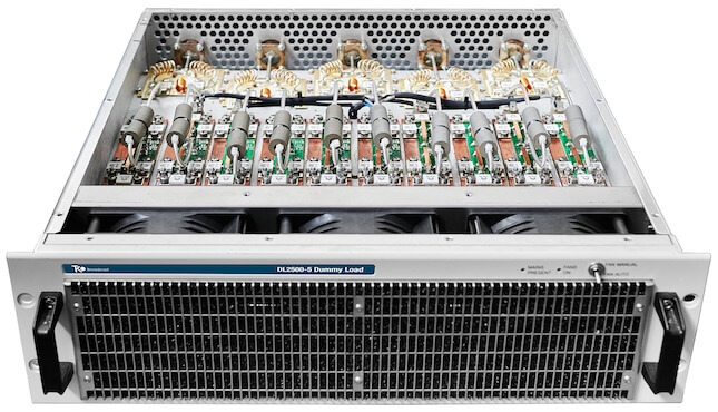
Over-Dimensioned Unbalanced Dummy Loads
The unbalanced dummy load is critical to system reliability. The CORTEX load features 1 to 5 inputs, depending on the number of RF modules, with each input rated at 6,000W—making it oversized by a factor of four.
In systems with more than five RF modules, multiple loads are used.
Typically, the maximum unbalanced power at each load input is around 1,300W, depending on how many modules are offline. For example, in a 10kW system with four 2,500W modules, the distribution varies based on module status.
Although the load is rarely stressed, it must be fully reliable when required. If under-dimensioned, it may overheat and fail, reflecting power back to active modules. This can trigger VSWR alarms and lead to shutdowns, compromising redundancy.
Some manufacturers address this by derating the remaining modules during a fault. This results in double power loss—from the failed module and the reduced output of the others.
When evaluating a transmitter, check whether derating is used during module failure, as it indicates inadequate load sizing.
A properly dimensioned unbalanced load must operate reliably under unbalanced conditions, prevent overheating and reflected power, and preserve redundancy and system stability.
Double Exciter with Automatic Changeover (Optional)
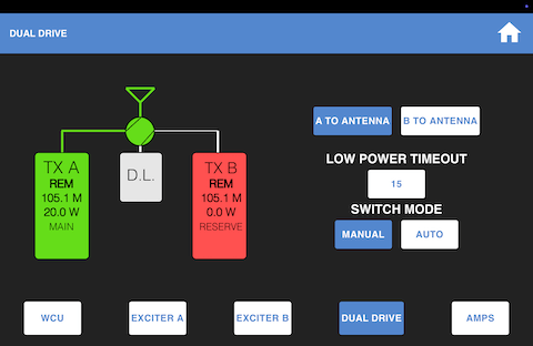
Automatically switches the backup exciter on-air, routing the faulty unit to a dummy load. The load enables testing and maintenance without disconnecting the transmitter.
Final test and Burn-In
An extended burn-in procedure is used to thoroughly test the transmitters over many hours of continuous operation, ensuring reliability and reducing the risk of faults caused by early component aging.
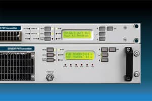
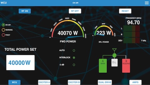
BRAIN WEB Remote Control
Touch screen graphic display provides intuitive local control and advanced remote access for precise diagnostics and efficient troubleshooting.
ADITIONAL FEATURES
Reliability and Robustness
- Engineered for Durability: All components are over-dimensioned for harsh conditions.
- Air Filter: Easy to clean or replace
- Aluminium Body: Light and strong
- Tropicalized PCBs and Wiring: Withstands extreme conditions
- Over-Dimensioned Components: Heatsinks, fans, LDMOS, dummy loads, power supply
- Integrated Protections: AC filtering, lightning, overvoltage spikes
- Mechanical Design: Compact 2U rack, optimized airflow, efficient heat management, durable fasteners
- Heavy-Duty Fasteners: 5 mm screws for secure assembly and easy access
- Optimized Cooling: Ducted airflow and dedicated heatsinks reduce thermal stress
N+1 and Backup Systems
- Supports multiple standby configurations
- No extra control unit needed
- N+1 connector with 7 profiles
- Relay outputs and opto-isolated inputs
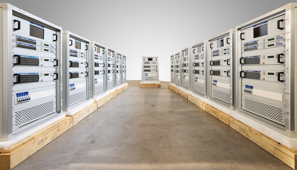
Packaging and Transport Protection
- High-quality packaging ensures resistance to shock, vibration, handling stress, and impact.
- Optimized weight and size facilitate logistics and make handling easier for operators.

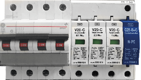
Integrated Protections
- Hardware protection (nanosecond response)
- Software derating (non-critical faults)
- Over-temperature and cooling failure detection
- Amplifier fault monitoring
- AC over/under voltage protection
- RF output open/short circuit detection
- AC mains filtering
- Lightning and surge protection
- Delayed energization and surge protection on the AC input prevent electrical stress during power-up and voltage transients.
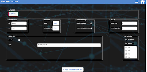
Dynamic RDS Encoder option
Fully dynamic FM broadcast RDS encoder with independent communication port
Control interface based on ASCII commands and UECP protocol
Text features include dynamic PS, parsing, scrolling, tagging, fixed messages, scheduling and HTTP reading
Excellent compatibility with broadcast automation systems
Control software includes powerful Windows GUI application
Supports control from external PHP/ASP scripts
Easy and fast set-up
Excellent spectral purity, direct digital RDS signal synthesis; compliant with EN 50067 / EN 62106
Two switchable program sets (with optional DSN and PSN setting)
Internal real-time clock incl. backup battery
No special 19 kHz input needed - pilot tone internally recovered from MPX signal using digital PLL