 BACK TO STL STUDIO LINK


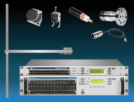
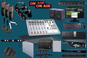
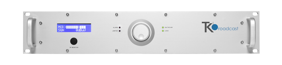
STL Studio Transmitter and Receiver Link
FM Radio Equipment
STL Radio Link Microwave Transmitter and Receiver:
Quality Audio Signals.
Our STL Link Transmitter and Receiver transports
Cristal and Clean, Quality audio signals from Studios
to Transmitter Sites several miles away.
Immediate delivery.
Designed to transport audio and video signals from the studio to transmission sites – maintaining high quality.
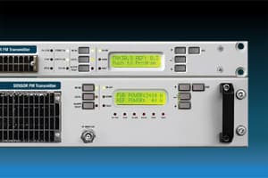
GENERAL DESCRIPTION
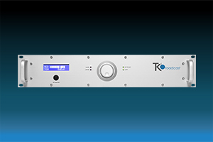
This transmitter and its companion the receiver
are the core of a high quality, synthesised studio-to-transmitter link
(STL), to be used for broadcast repeaters in conjunction with any
standard FM or AM transmitter.
They are an evolution of the previously
established STL series, whose main circuitry is still extensively used
here with a new controller, user interface and software, and more
advanced oscillators in a compatible 2u 19" case.
These allow the reception of mono or stereo signals and its retransmission without
using any additional stereo-coder on the receiving end; in both cases,
the LF output signal from the receiver must be sent to the stereo
input (linear or not pre-emphasised) of the local FM rebroadcast
transmitter.
The STL is built for several different frequency slots, from the VHF to
the SHF range.
Two main models are built: one for the 200-960 MHz range, and
the other for the 1300-2500 MHz one.
While the exterior cabinet, the controls, the basic circuitry and the performances are the same, some
internal components vary or are specifically tuned as required to
cover this wide frequency band.
Usually, these components are: the local oscillator, the power amplifier and the input/output filters.
The factory adjusted frequency slots are 10 to 50 MHz wide and must be
specified in the order.
In the preset sub-range, the frequency and
power of the transmitter may be freely changed on the site.
The receiver may require some more adjustment for wider frequency
displacement: in fact, the adoption of narrow, low loss input filters
permitted to achieve the best possible rejection of interfering
signals in the band at the expense of some frequency agility.
So, nearly 8-10MHz may be used without any retouching, but wider variation
up to 50-60MHz will require retuning of the input filter.
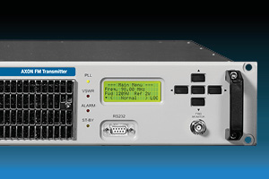
Being the apparatuses completely digitally controlled, they are
extensively programmable on site via the front panel, or remotely, in every
respect.
The alphanumeric display permits easy and accurate metering,
adjustment and continuous monitoring of modulation levels, power,
operation and internal parameters. All this information is
externally available via the same RS232 I/O port, which may be used to
remotely control the transmitter.
In addition to the serial I/O, some signals and controls are available on a parallel I/O socket for easy interfacing with other analog controllers or supervisory systems.
A powerful 3-level password management permits a very high degree of security and privacy as may be required in different situations.
The LF input and output levels are precisely adjustable over a broad
range, by means of 0.5dB stepwise variable attenuators.
The transmitter has also an auxiliary input, specifically designed for RDS
and SCA encoders.
A modulation monitor output permits to control other
transmitters or STL's with the same internally processed high-quality
MPX signal.
Furthermore, the system is optimised to be compatible with
external digital companding encoder/decoders and to provide RDS and
SCA signals, with almost no attenuation.
Optional top-quality stereo encoder/decoder boards may be factory
installed on the transmitter/ receiver or field retrofitted with
minimum required technical skill.
The powerful internal software and monitoring functions recognise their presence and enable the functions.
A universal switch-mode power supply permits operation in
the extended 95-250 V ac range with no intervention, and a 24 V back-up
battery input is also provided.
DESIGN
These radio links were specifically designed to comply with the latest international standards and the requirements of advanced broadcasters, meeting tighter specifications than usually required, at an affordable cost.
Great care was spent into producing a Hi-Fi-quality modulated signal, with low residual noise and distortion. The RF signal is also free from spurious and harmonic components to a higher degree than required by CCIR, European, USA and most other national standards.
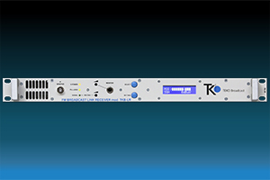
RECEIVER RADIO LINK MODELS
| MODEL | DESCRIPTION |
|---|---|
| TK-STL-R1 | Link Receiver Band 170 - 490MHz (band max ±10MHz) |
| TK-STL-R3 | Link Receiver Band 820 - 960MHz (band max ±10MHz) |
| TK-STL-R5 | Link Receiver Band 1.4 - 2.5 GHz (banda max ±5MHz) |
RADIO LINK RECEIVER: TECHNICAL FEATURES
| PARAMETER | VALUE |
|---|---|
| Frequency Ranges | 200~960 MHz - 20MHz sub-band |
| Type of Modulation | FM Class F3 |
| VCO Tuning | 25 MHz |
| Frequency Stability | ± 2.5 ppm (Better on request) |
| Synthesizer | Step 25KHz |
| Image Rejection | 60dB Typ. |
| RN Noise Figure | 6dB or lower |
| Stereo Separation | > 45 dB @ 1 KHx |
| Distorsion | < 0.5% (TYP 0.2 % @ 1KHz) |
| Base Band | 30 Hz - 60 KHz within 0.08 dB |
| S/N Ratio | > 72 dB with 0.2 mV input (Typ 78 dB) |
| Deenphasis | 50 or 75 μS int. selectable |
| RF Connectors | N-F 50 ohm |
| B. Band-IF Conn. | BNC-F |
| Base-Band Imp. | < 30 ohm |
| Cooling | Forced air |
| P. Temp. Range | 0 ÷ +45°C |
| Maximum Umidity | 90% |
| AC Supply | 100 ÷ 240 Volt; 47 ÷ 63 Hz |
| Dimension | 1 Units Rack 19” 44 cm Depth |
| Weight | 5.8 Kg |