

STL Studio Transmitter Link Equipment
Frequency Range: 170MHz - 2.5GHz
Transmitters, Receivers and Amplifiers to link the Studio to the Radio Station
Transport HIGH QUALITY audio signals from the studio to transmission sites.
Wide selection of Frequency Band and Power.
Long distance coverage.
GENERAL DESCRIPTION
This Transmitter and its companion the Receiver
are the core of a high quality, synthesised Studio-to-Transmitter Link
(STL link), to be used for broadcast repeaters in conjunction with any
standard FM or AM transmitters.
They are an evolution of the previous established STL series, whose main circuitry is still extensively used
here with a new controller, user interface and software, and more
advanced oscillators in a compatible 2u 19" case.
They allow the reception of mono or stereo signal and its retransmission without
using any additional stereo-coder on the receiving end. In both cases,
the LF output signal from the receiver must be sent to the stereo
input (linear or not pre-emphasised) of the local FM rebroadcast
transmitter.
The STL is built for several different frequency slots from the VHF to
the SHF range.
Two are the main models that we build: one for the 200-960 MHz and the other for the 1300-2500 MHz range.
While the Exterior Cabinet, the Controls, the Basic Circuitry and the performances are the same, some internal components vary or are specifically tuned as required – to cover this wide frequency band.
Usually, these components are the Local Oscillator, the Power Amplifier and the Input/Output Filters.
The factory adjusted frequency slots are 10 to 50 MHz wide and their order must be specified.
In the preset sub-range, the frequency and power of the transmitter may be freely changed on the field. The
receiver, on the other hand, may require some more adjustments for wider frequency
displacements; in fact, the adoption of narrow, low-loss input filters
permit to achieve the best possible rejection of interfering
signals in the band at the expense of some frequency agility.
In other words, nearly 8-10MHz may be used without any retouching, but wider variations up to 50-60MHz will require a retuning of the input filter.
Being the apparatuses completely digitally controlled, they are
extensively programmable on field, using the front panel or remotely, in every
respect.
The alphanumeric display permits easy and accurate metering,
adjustment and continuous monitoring of modulation levels, power,
operation and internal parameters.
All this information is externally available on the same RS232 I/O port that may be used to
remotely control the transmitter.
In addition to the serial I/O, some signals and controls are available on a parallel I/O socket, for easy interfacing with the other analog controllers or supervisory systems.
A powerful 3-level password management permits a very high degree of security and privacy, as may be required in different situations.
The LF Input and Output Levels are precisely adjustable over a broad range, by means of 0.5dB variable stepwise attenuators.
The transmitter also has an auxiliary input, specifically designed for RDS
and SCA encoders.
A modulation monitor output permits to control other
transmitters or STLs with the same internally processed high-quality
MPX signal.
Furthermore, the system is optimised to be compatible with
external digital companding Encoders/Decoders, and to provide RDS and
SCA signals, with almost no attenuation.
Optional top-quality Stereo Encoder/Decoder Boards may be factory
installed on the Transmitter/Receiver, or field retrofitted with
minimum required technical skill.
The powerful internal software and monitoring functions recognise their presence and enable the
functions.
A universal switch-mode power supply permits operation in the extended 95-250 V ac range with no intervention, and a 24 V back-up Battery Input is provided too.
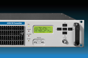
TECHNICAL FEATURES: THE TRANSMITTER
The Transmitter and Receiver Sets are fitted in the same-sized cabinet and are nearly identical from the front. They only differ for the name in the front panel and the display, and for the rear panel's connector accommodation.
Both pieces of equipment are clean and easy to control from the front panel through a single knob.
The wide alphanumeric display and a simple self-explanatory menu drive the navigation through the various options.
A single push on the jog knob acts as "Enter" or confirmation – while holding it is interpreted as "Escape".
Some leds signal proper functioning, while others are to be interpreted as warning status.
Two red leds signal the warning status: "Alarm"and"Limiter".
A bi-stable yellow/green led signals"On-air", while a fourth one signals "PLL Lock"; both of these two should be green when the operations are running correctly.
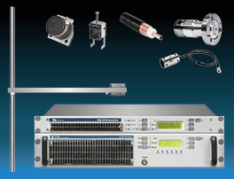
All equipment Inputs and Outputs except for the RF monitor are allocated in the rear panel.
These are:
- The Main Supply IEC320-type outlet, which incorporates the main switches and the fuses. An additional Earth Screw for system earthing and a 24V= battery backup Socket Pair. In alternative, the main outlets with fuse-holder and the main switches may be separate components;
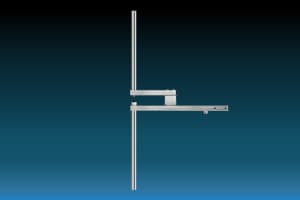
- The RF Antenna Connector – N-type;
- The L & R Stereo Analog Audio Channels Input on balanced XLR-type connectors (the L input is used only with the internal Stereo Encoder option);
- The AES/EBU Stereo Digital Audio Input on a balanced XLR-type connector, which may be used as an alternative to the Analog Input (this is a special option and may be used only in conjunction with the internal Stereo Encoder option);
- The Wide-Band Externally Processed Stereo or Composite Signal Input on a grounded unbalanced BNC connector;
- A Frequency-Limited (20k-100kHz) Auxiliary Channel Input on a grounded, unbalanced BNC connector for an RDS or SCA signal;
- An LF Modulation Output for monitoring, RDS external synchronisation or re-broadcasting purposes – BNC-type;
- A RS232 Dsub9 Female Remote Serial Control Port, inverted wired;
- A Parallel Control Port, Dsub9 male type.
No internal or external preset is needed to correctly perform on the 110 - 240V main range.
TECHNICAL FEATURES: THE RECEIVER
Like the Transmitter, the Receiver's front panel accommodates the single control knob, the display, four leds for immediate status control and a single output connector for IF monitoring.
Here too, regular operation is signalled by green leds: "PLL Lock"
and "Field". This latter is a bi-stable and is signalled by a yellow light when the RF
field is too low or absent.
As for the Transmitter, red leds signal improper operation. The first one, "Modulation", is activated by low
or absent modulation; the last one is the general "Alarm" led.
The Receiver I/O connectors on the rear panel are:
- The Main Supply IEC320-type Outlet, which incorporates the main switch and the fuses. An additional Earth Screw for system earthing and a 24V-battery backup Socket Pair. In alternative the main outlets with fuse-holder and the main switch may be separate components;
- The RF Antenna Connector, N-type;
- The Main Composite Signal Output (Mpx+, Mpx-) on two BNC-type connectors in antiphase, permitting direct drive of two separate transmitters or one in balanced mode;
- A Buffered LF Monitor, BNC-type Connector that may be internally connected as an additional composite or wide-band or mono signal output;
- The Filtered/de-emphasised Mono Signal on a balanced male XLR-type connector;
- The L & R Audio Channels Output Sockets on balanced XLR-type connectors (only with an internal Stereo Decoder option);
- A RS232 Dsub9 Female Remote Serial Control Port, inverted wired;
- A Parallel Control Port, Dsub9 male type.
DESIGN
These radio links were specifically designed to comply with the latest international standards and the requirements of advanced broadcasters, meeting tighter specifications than usually required, at an affordable cost.
Great care went into producing a Hi-Fi-quality modulated signal,
with low residual noise and distortion.
The RF signal is also free from spurious and harmonic components to a higher degree than required
by CCIR, European, USA and most other national standards.
TRANSMITTER RADIO LINK MODELS
| MODEL | DESCRIPTION |
|---|---|
| TK-STL-T1-10 | Link Transmitter Band 170 - 490MHz (band max ±10MHz), 10W |
| TK-STL-T3-10 | Link Transmitter Band 820 - 960MHz (band max ±10MHz), 10W |
| TK-STL-T1-20 | Link Transmitter Band 170 - 490MHz (band max ±10MHz), 20W |
| TK-STL-T3-20 | Link Transmitter Band 820 - 960MHz (band max ±10MHz), 20W |
| TK-STL-T5-5 | Link Transmitter Band 1.4 - 2.5 GHz (banda max ±5MHz), 5W |
RECEIVER RADIO LINK MODELS
| MODEL | DESCRIPTION |
|---|---|
| TK-STL-R1 | Link Receiver Band 170 - 490MHz (band max ±10MHz) |
| TK-STL-R3 | Link Receiver Band 820 - 960MHz (band max ±10MHz) |
| TK-STL-R5 | Link Receiver Band 1.4 - 2.5 GHz (banda max ±5MHz) |
AMPLIFIER RADIO LINK MODELS
| MODEL | DESCRIPTION |
|---|---|
| TK-STL-A1-50 | Link Amplifier Band 170 - 490MHz (band max ±10MHz), 50W |
| TK-STL-A3-50 | Link Amplifier Band 820 - 960MHz (band max ±10MHz), 50W |
| TK-STL-A1-100 | Link Amplifier Band 170 - 490MHz (band max ±10MHz), 100W |
| TK-STL-A1-200 | Link Amplifier Band 170 - 490MHz (band max ±10MHz), 200W |
| TK-STL-A5-20 | Link Amplifier Band 1.4 - 2.5 GHz (banda max ±5MHz), 20W |
STL – Studio Transmitter Link: Description
The RF signal is also free of spurious and harmonic components to a
degree greater than that required by CCIR, Europe, USA and most
other national standards.
Maximum attention has gone into producing a modulated signal of High Fidelity and Quality, with a high noise
signal ratio and a very low distortion.
The TK-STL-TX Transmitter and its TK-STL-RX Receiver are the basis of a high quality synthesized link (STL), which is used to transport the signal from the studio to the radio transmitter, or for repeaters with FM or AM modulation.
They allow the reception of mono or stereo signal and its retransmission without using any additional stereo encoder at the receiving end. In both cases, the LF output signal of the receiver can be connected directly to the MPX input of the transmitter or the local FM relay.
The STL is built for several frequency bands in the SHF range.
These radio links were designed to meet modern international standards and the requirements of existing broadcasters, complying with strict specifications at an affordable cost.
Since they are digitally controlled, they can be programmed on the radio station from the front panel or remotely.
The alphanumeric display allows you to measure, adjust and monitor modulation levels, power and operating parameters.
All this information is available externally through the RS232.
The Low Frequency Audio input and output levels are precisely adjustable over a wide range by means of variable attenuators.
The transmitter has an auxiliary input for RDS and SCA encoders.
A modulation monitor output allows other transmitters or STLs to be fed with the same high quality MPX signal processed internally. In addition, the system is compatible with external digital encoders / decoders that provide RDS and SCA signals without attenuation.
A universal switched power supply allows operation in the extended range of 95-250 VAC without intervention, and a 24V backup battery input is also provided.
STL – Studio Transmitter Link: Highlights
- Synthesized from 48 to 900 MHz and from 1.2 to 2.7 GHz (/ 2G models). The transmitted and received frequencies can be easily set from the front panel display. Changing frequency is very simple and easy thanks to frequency synthesis with 10 kHz steps and to the simplified calibration of the input filter;
- It is possible to vary the output level of the demodulated signal from –12dBu to + 12dBu with 0.1 dB steps and a 0.03 dB precision; the received signal level can be measured on a dBm scale (as on a spectrum analyzer) on which the squelch intervention threshold can be set;
- Excellent stereo separation. A built-in group delay and amplitude pre-corrector guarantees a very low linear distortion and a great stereo separation in the whole 15kHz band;
- Suitable for digital audio. The subsonic over-modulation and the low frequency phase distortion are controlled by a feedback circuit in order to exalt the audio quality of the latest digital systems;
- Low noise. The excellent signal-to-noise ratio either in mono or in stereo guarantees a perfect use of this STL in multi-hop networks without compromising the audio quality;
- High sensitivity. Using ultra low noise amplifiers, selective filters and a powerful demodulation circuit, the obtained receivers sensitivity is very high, thus allowing longer link distances with a reduced antenna investment;
- Great RF immunity allows to operate in most hostile RF environments;
- High adjacent Channel Rejection, obtained thanks to the excellent mechanical shielding and the precision of RF filtering;
- High Frequency Stability with the internal temperature compensated crystal reference;
- Simple and clear Menus on an LCD graphic display allow to control
all the main functions of the receiver and to precisely measure main
parameters such as frequency deviation, MPX pilot tone deviation, the
received signal level and squelch level.
Full metering: complete diagnostic and measurement of all the main parameters is available using the front panel LCD display. Full remote control is available as an option.
Provided with a battery to ensure continued functioning even in the absence of power supply and it’s provided with alarm outputs for remote control. A VDC power supply option is available for battery or solar panel operations. It meets or exceeds all FCC and CCIR requirements. - Components of the best brands and the newest and well-proven technologies have been employed to grant continued functioning of the receiver, high selectivity and immunity to adjacent signals and a higher audio quality.
- The exclusive system of module removal for easy maintenance and / or internal inspection without removing panels completes a unit suitable for all requirements.
RADIO LINK TRANSMITTER: TECHNICAL FEATURES
| PARAMETER | VALUE |
|---|---|
| Frequency Range | 200~960 MHz -20MHz sub-band |
| Type of Modulation | FM Class F3 |
| VCO | Tuning 25 MHz |
| Frequency Stability | +/- 2,5ppm (Bettr 0n request) |
| Synthesizer | Step 25KHz |
| Power | Output 10 Watts |
| Spurious Emission | < -80 dB or better |
| Harmonic Emission | < -65 dB (-80 dB on request) |
| Stereo Separation | > 55 dB @ 1 KHz |
| Distorsion | < 0.2% (TYP 00.8 %) @ 1KHz) |
| Base Band | 30 Hz - 60 KHz within 0.15 dB |
| Unweighted | S/N Ratio > 74 dB rms at 30 Hz ~ 20 KHz |
| Enphasis | 50 or 75 us selectable |
| RF Connectors | N-F 50 ohm |
| Input Base Band Imp. | 2 Kohm |
| Input Mono Impedence | 600 Ohm |
| Cooling | Forced air |
| OP. Temperature Range | 0 ÷ +45°C |
| Maximum Umidity | 90% |
| AC Supply | 100 ÷ 240 Volt; 47 ÷ 63 Hz |
| Dimension | 1 Units Rack 19†44 cm Depth |
| Weight | 6.5 Kg |
RADIO LINK RECEIVER: TECHNICAL FEATURES
| PARAMETER | VALUE |
|---|---|
| Frequency Ranges | 200~960 MHz - 20MHz sub-band |
| Type of Modulation | FM Class F3 |
| VCO Tuning | 25 MHz |
| Frequency Stability | ± 2.5 ppm (Better on request) |
| Synthesizer | Step 25KHz |
| Image Rejection | 60dB Typ. |
| RN Noise Figure | 6dB or lower |
| Stereo Separation | > 45 dB @ 1 KHx |
| Distorsion | < 0.5% (TYP 0.2 % @ 1KHz) |
| Base Band | 30 Hz - 60 KHz within 0.08 dB |
| S/N Ratio | > 72 dB with 0.2 mV input (Typ 78 dB) |
| Deenphasis | 50 or 75 μS int. selectable |
| RF Connectors | N-F 50 ohm |
| B. Band-IF Conn. | BNC-F |
| Base-Band Imp. | < 30 ohm |
| Cooling | Forced air |
| P. Temp. Range | 0 ÷ +45°C |
| Maximum Umidity | 90% |
| AC Supply | 100 ÷ 240 Volt; 47 ÷ 63 Hz |
| Dimension | 1 Units Rack 19” 44 cm Depth |
| Weight | 5.8 Kg |